Mentor Graphics’ Valor MSS is one of the most efficient tools available for PCB assembly, and offers complete end-to-end...
READ MORE


Placing pins can be one of the most time consuming aspects of library part creation – especially on components with high pin counts or unusual pinouts. One way to speed up the process of making these components is to place pins according to a set pattern. Let’s take a look at a few different instances where pattern place can speed up part creation.
NOTE: This guide assumes a basic understanding of Mentor’s Library Manager and Cell Editor.
In this example we’ll build an 8 pin SOIC, datasheet available here. Lets get started.
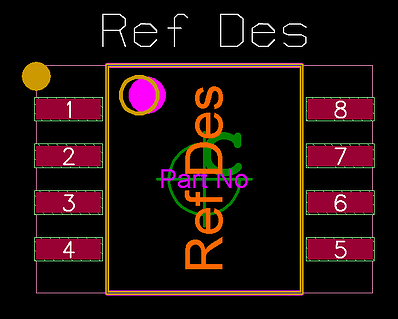
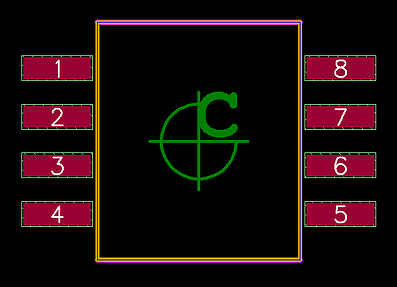
- Create the body of the component and the necessary layers. The part should now look like this:


- Click the Place Pins button.

- The Place Pins dialog box will appear, choose the appropriate padstack for the part. Per the land pattern in the Datasheet (pg. 32), we want padstacks that are 1.75mm long by .55mm wide.
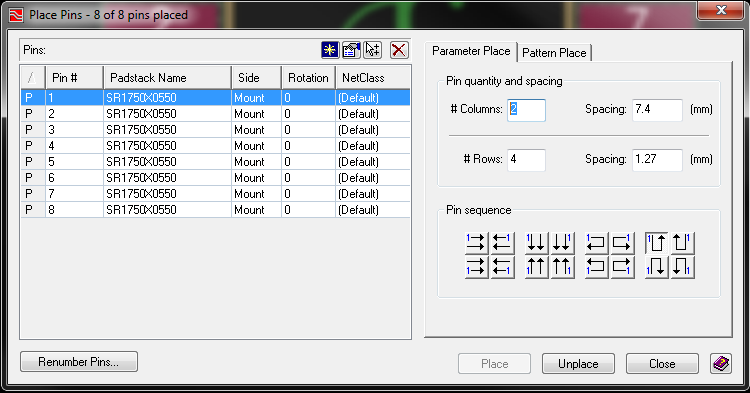
- Note the Parameter Place and Pattern Place options in the Place Pins dialog box, for this part we’ll use the Parameter Place tool.
- Two measurements from the datasheet are necessary, pin pitch (in this case 1.27mm) and the distance between each row of pins (7.4mm). Enter these measurements into the Columns, Rows, and Spacing fields. NOTE: The pin to pin distance must be from the center of the pin, not an edge.
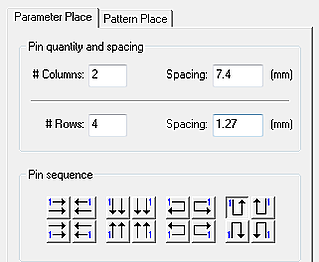
- Select the appropriate Parameter for pin placement. The pin numbering of the component determines the parameter you need to use. Match the pattern of the numbering to the Parameter in the dialog box. In this instance we’ll use a Parameter that places pin 1 at the top left of the component, and wraps around its body in a U shape. (See above image, with the parameter button depressed).
- Select all pins in the section at left, and click the place button. The Place Pins dialog will disappear, and a hollow version of the pins, with pin 1 below your cursor, will appear.
- Before clicking to place the pins, press the X-Y Place button at the bottom of the Cell Editor Window, or press F3. The X-Y Place dialog will appear.
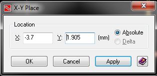
- Calculate the position of pin 1 based on the information given on the Datasheet, and enter it into the X and Y dimensions in the dialog box. Note: Being sure that the Origin is directly in the center of the component body simplifies this step.
- Click apply and the Place Pins dialog box will re-appear, indicating your pins have been placed. Your component should now look like this:
- Draw the necessary pin 1 indicators (assembly and silkscreen corner fill, and dot next to pin 1. Draw the DFA_Bound_Top box around the entire body of the component, and it is now complete. The finished product should appear as follows, and is ready for checking and use in designs.